


The internal decisions and technical details of the units.
From the beginning of testing it became clear the unit would substantially outperform expectations, not only was it very light (under 12kg) but very powerful.
THREE unusual steps were taken to improve performance over any other semi transportable amplifier as well as the very conservative “mil” factory specs:-
1/ The use of a pentode rather than a beam tetrode, and to opt for parallel push pull (PPP)*, effectively extending class A performance to very high output levels.
This is a world first.
Nobody ever used these superb valves as a PPP* quad before.
Now, note some of the military “high reliability” specs:-
All valves are WIRED ENDED, soldered solidly into tag boards, so there are NO SOCKETS.
Not a single valve can be thrown out of a socket or have bad contacts because there are NONE.
In addition:-
All the valves are guaranteed to stand over-voltage on the series connected heaters and decelerations of more that 100g.
There is NO internal power supply, so the large PSU is placed far away from the unit, where it is optimal, and doesn’t add extra heat.
One of an identical pair.(Quads are selected out from 50 NOS valves)

This painstaking selection substantially improves linearity & gives a spectacular drop in IMD.
In this case a pair at low voltage (165V**) was forecast to give 13W.
Because we opted for PPP* we could lower the A-A load and drive a lot more current through the oversized output transformer.
Our PPP quad was adopted with TWICE this voltage**, giving twice the gain and 4x the output.
They appeared quite happy & safe at 500V and 60W output, and could handle nearly 1/4 amp at that voltage.
2/ The decision to abandon cathode bias, and to use a fully stabilised fixed bias system using multiple series zener diodes.
The full quad of valves per channel (total 8 for stereo) is then selected out to be absolutely identical.
This also dropped the distortion by a large amount and increased power output.
The Tag boards are all seperate for voltage stabiliser and each output channel, enabling quick and easy replacement if needed.
The beautiful avionics output pentodes glowing

3/ The decision to use a fully stabilised screen grid supply for the output valves. The stabiliser valve, – also mil spec is fed by a pair of 150V russian mil spec miniature voltage stabilisers.
The beautiful mil spec power triode stabiliser detail

The little russian mil spec glow tubes glowing

In normal circumstances it’s recommended to keep the screen voltage to within 3% for best distortion on a high power amplifier.
With our simple but effective triode cathode follower circuit we got only 2V variation at the screen grid, a variation of 0.7%, from idle to full load, and a low drive impedance of 850 ohms.
4/ The decision to use ONLY cathode feedback to linearise the amplifier rather than global NFB or ultralinear connection.
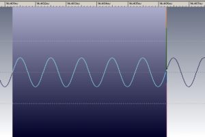
400hz sine
This proveably made the frequency response flat to 22khz, reduced THD and IMD to completely inaudible levels and made the whole amplifier ultra stable under any load.
Here are some of the most critical photos showing the linearity remaining substantially identical from almost zero to within 1dB of maximum output.
1khz square

The square wave test is especially impressive, bearing in mind the ESL drive elements are actually capable of reproducing it.
This equates in a car to an impossibly high 100W RMS when running both channels to maximum.
Passing this level, the amplifier clips softly & progressively without the nasty harshness seen in solid state devices.
NOTE:-
This unit has NO Chinese or Asian parts.-
It is almost entirely British made.
Bear in mind this amplifier is fully mobile, can be transported in a flight case, used with no 220V power source and will easily compete with a Marshall 100W guitar amplifier, while giving stellar frequency response, low noise and ultra low distortion.
This is what Aston Martin and Jaguar were designed for.